OBD2b to OBD1 swap (D14Z1)
I recently swapped to a P06 ECU on my D14Z1 to make adjust the motormanagement with CROME. Therefore I placed a D16Y8 intake manifold on my D14 head. And I also changed the complete exhaust line to get a better flow. I had 123,6hp @ 7000rpm and 141Nm @ 5700rpm on the dyno after this modifications.
What did I used for the ODB1 swap?
- Boomslang conversion harnass (www.boomslang.us)
- ODB2 240cc injectors
- P06 ECU (non-vtec) with CROME
- www.dodo-upgrades.nl - the Dutch D14 king ;-)
This is the pinout of my connectors:

Nomenclature:
ACC - A/C relay
ACS - A/C switch
ALTF - Alternator switch
BKSW- Brake switch, for control purposes, not present on all ECU’s
CKF - Crankshaft speed, (P)ulse or (M)ass, gives 12 pulses by LED during each crank shaft rotation
CKP - Crankshaft position, (P)ulse or (M)ass, gives several pulses (~20?) during each cam shaft rotation
CYP - Cylinder position, (P)ulse or (M)ass, gives one pulse during each cam shaft rotation
DLC - Diagnostic connector, communication signal to the 3 wire connector next to the SCS connector
ECO - ECONOMO light
ECT - Engine coolant temperature
FLR - Fuel relay
IACV - Idle air control valve, controls the 2 wire type IACV valve
IAT - Intake air temperature
ICM - Ignition pulses, 1 is always present, 2 can be ignored
IGP - Battery feed, only active when key is turned
IMO. - Checks IMO code of the key and activates FLR if correct
INJ - Injector, the number refers to the cylinder used (1 is on the side with the belts)
INOCD- Checks IMO code of the key and activates FLR if correct
LG - Ground for battery circuit
MAP - Manifold absolute pressure
MIL - Motor indication light, this one gives the control engine light (CEL) signal
NEP - Signal to engine speedometer
PCS - Control solenoid, this one is for the small black cylindric valve on the back of the IM
PG - Ground for battery circuit
PO2H - Primary oxygen sensor heater, connects with the ground of the car to activate the heater
PO2S - Primary oxygen sensor signal
SCS - Service connector switch, checks if the SCS connector is hot wired (for reading engine error codes)
SG - Ground for 5V circuit, 1 is for the MAP sensor, 2 is for the other sensors
STS - Starter switch
TDC - Top dead centre, (P)ulse or (M)ass, gives four pulses during each cam shaft rotation
TPS - Throttle position signal
VBU - Back up battery feed, always active (unless battery is removed)
VCC - 5V feed, 1 is for the MAP sensor, 2 is for the other sensors
VSS - Vehicle speed sensor
What won't be used in the obd1 situation (not connected)?
- IMO/INO: Checks IMO code of the key and activates FLR if correct, OBD1 misses this safety!
- IACV: Idle air control valve, controls the 3 wire type IACV valve, (N)egative and (P)ositive control (== RACV)
- CKF: Crankshaft speed, (P)ulse or (M)ass, gives 12 pulses by LED during each crank shaft rotation
Fix your IACV control!
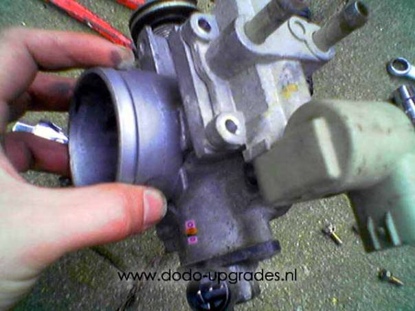
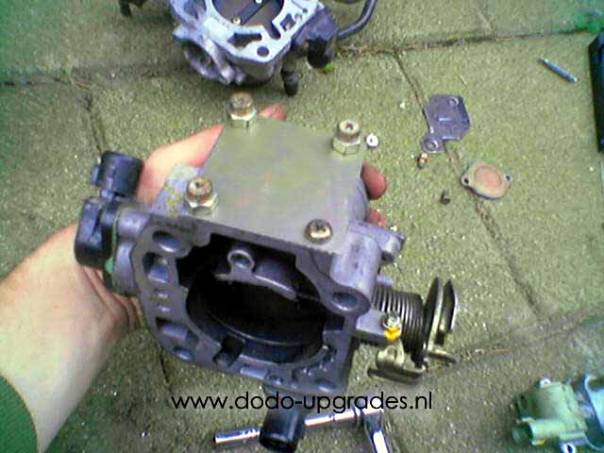
The conversion harnass is easy to install. Just click in the connectors. The only thing you have to modify is the IACV connection. I have my original D14 throttle body with a RACV (Rotary Air Control Valve) sensor. You have to remove this sensor en take the wires from it to connect it to your IACV sensor on your D16 intake manifold (if you have your original intake manifold, swap your intake manifold!!!). Your IACV sensor will only have 2 wires, the RACV sensor has 3 wires. 1 wire will not be necessary. Just connect the black wire to the IACV sensor and the orange or black/bue wire to the IACV sensor.
Removing the RACV sensor and place a nice piece of metal instead:
A last tip on the OBD1 swap: adjust the ignition timing to 16 deg BTDC, this is the normal timing of OBD1 engines. The marks on the D14A3/A4 crank pulley are 10, 12 and 14. So you should time the ignition (using a stroboscope) a little bit before the 14 deg mark passes.
Don't forget to visit http://www.dodo-upgrades.nl for more D14 power!
Question? My e-mail adress is: sebastian.hagens@gmail.com